
Maintaining target operating conditions
In the manufacturing industry, process safety is paramount. And by process safety, I mean the safety of the equipment used in your process. Process equipment is designed to operate at a target set of operating conditions. Sometimes, however, the process can deviate outside of those limits and create major headaches for the facility.
Layers and layers of protection
Plants rely on instrumentation in the form of pressure transmitters and temperature transmitters to monitor the state of their processes. There are usually layers upon layers of safety features built into the design of the process. One of these layers is the rupture disc.
Tin foil to save vessels, really?
A rupture disc is essentially tin foil. Yes, really! It’s a very thin piece of metal that has been precisely engineered to respond to the slightest hint of pressure build up inside a vessel or reactor. The beauty of the rupture disc is that it does not rely on an external input to work. As such, a rupture disc is known as a passive safety device.
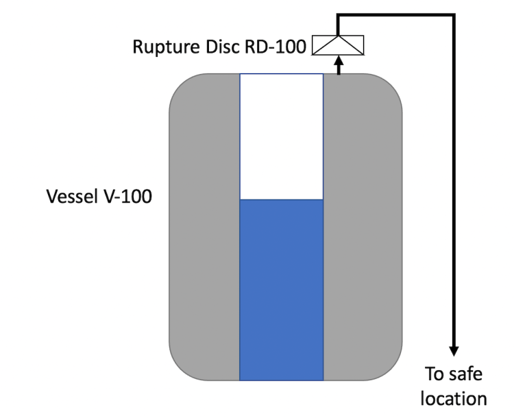
The image below (Figure 1) shows a high level representation of the rupture disc RD-100 on Vessel V-100. The rupture disc is indicated with the commonly used “triangle-inside-a-rectangle” drawing symbol.
How does a rupture disc work?
The most important feature of a rupture disc is its burst pressure. This is the pressure at which the disc will actually burst or break. Doing so, allows the reactor or vessel that it protects to de-pressure rapidly and return to normal operating conditions as fast as possible.
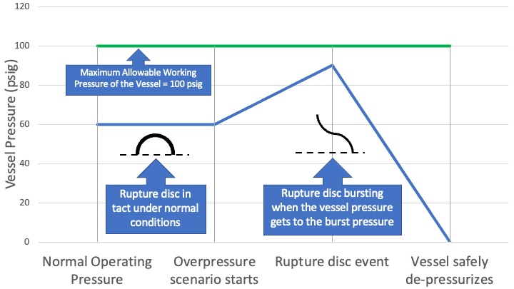
In the examples below, the top image (Figure 2) shows the timeline of a normal rupture disc event. In this scenario, the rupture disc activates as designed when the vessel reaches the burst pressure of the rupture disc.
Note: In Figure 2, the rupture disc is shown as a semi-circle which more closely matches what it looks like in real life, versus the drawing symbol shown in Figure 1.
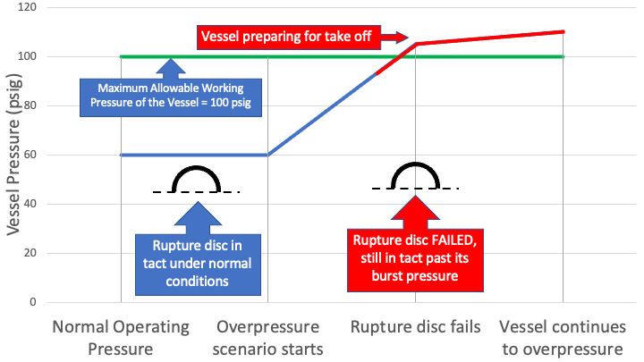
The bottom image (Figure 3) shows the timeline of a rupture disc failure. In this scenario, the rupture dic fails to respond at its burst pressure and never activates. The vessel continues to increase in pressure, and without additional intervention, prepares to take off.
Now, of course, you don’t ever want your reactor or vessel to get to a point where it starts to increase in pressure unchecked. However, if that does occur, you want to be sure your rupture disc will respond as designed.
It takes more than just a working rupture disc
As you can imagine, if a rupture disc does not respond to a spike in pressure as designed, the results can be catastrophic. Think of a reactor turning into a canon ball. Not good. Not good at all.
It’s not just the design of the rupture disc that’s important. Proper installation technique and optimal storage conditions are also important. You don’t want to find out that your reactor or vessel is not protected the hard way. When your reactor or vessel is preparing for take off because its internal pressure has nowhere to go, it’s too late.
Proper rupture disc storage and installation
Proper storage
As I said, a rupture is essentially tin foil. Proper storage of rupture discs is essential. You don’t want rupture discs laying around outside of the original packaging that it came in. The semi-circle shape of the rupture disc must be maintained for proper operation. Any dimples or dents compromises the ability of the rupture disc to activate at its burst pressure.
You also don’t want to store rupture discs at excessive temperatures. It’s metal. And metal deforms above certain temperatures. Ambient room temperature is the way to go when storing rupture discs.
Proper installation
Proper installation of rupture discs is also essential. In one situation I was involved in, we kept running into multiple rupture disc failures every other month. The puzzling thing was the rupture discs were bursting at pressures well below their burst pressure. Turns out, the rupture disc itself was just fine. It was the rupture disc holder that was the issue.
Tri-clamps had been used in the past as rupture disc holders when installing rupture discs. Tri-clamps are commonly used to connect two pieces of pipe together and secured by hand-tightening. However, the rupture disc vendor recommended specially made torque clamps which allowed you to tighten the clamp to a specific setting. Torque is a defined unit of measure of how tightly a piece of equipment has been tightened. Once we switched to these torque clamps, the issue magically disappeared.
It wasn’t magic at all. It was great collaborative team work. It was a great win!
Putting it all together in writing
To keep the win going, we needed to document this critical change to how we did things. Or else, we were going to be right back where we started.
The first place I targeted was the site’s procedure on rupture disc installation. This document did not clarify that special torque clamps were required for rupture disc installation. I updated the SOP to reflect the use of these special torque clamps. I also included the associated torque ratings. Different size rupture discs require different torque settings.
The site’s technicians are the ones who installed the rupture discs at this site. They use work orders routinely. The work order is a paper (or electronic) form that tells the technician the scope of their work. The work order includes equipment location and type of maintenance work required. That was the next document I updated to include:
- Date of installation
- Initial of technician performing the installation
- Serial number of the rupture disc being installed
- Equipment number where the rupture disc was being installed
- Torque setting used
That’s just 5 things.
We went a whole year without another rupture disc incident. That’s 12 months.
That’s 12 months I didn’t have to schedule another hour long Root Cause Analysis (RCA) meeting with 10 people on this recurring issue. That’s 10 people and their valuable time back every other month. That’s 600 hours back.
In the middle of a global supply chain crisis, replacing these rupture discs every other month was not sustainable. Each rupture disc cost ~$1000 each and had to be ordered at a minimum quantity of 5 at a time. That’s $5000 saved.
Every time a rupture disc burst, the associated equipment had to be taken down, isolated and cleaned before returning to service. With this win, that was 12 months of uninterrupted service for the plant. The impact to the bottom line was huge. The equipment manufactured a blockbuster product that earned $8 billion in annual revenue. Yep, that’s $8 billion with a “b” in revenue earned.
Collaborative team work allowed the plant to achieve a huge win (well yours truly did most of the investigating, ahem). But effective documentation sustained that win, and will do so for many years to come.
This article is also published on Linkedin.
